Controllers
This section contains the description of all controllers implemented in VSlib.
General interface
All controllers described in further detail below, the RST and PID, are both derived from and implement the Component interface. They have a number settable Parameters that need to be defined before the component can be used.
The two distinct components serve only as an interface for your convenience, as they both use the same
engine, that of an RST controller. Both components include a LimitRange component
to provide saturation protection and ensure that the actuation provided by the controller falls within the expected range.
Both components have a single access method to return the next double-type actuation value called control,
that takes two arguments of type double: current reference (set-point) and current measurement (process value) values.
In case of and RST, the control method will return 0.0 until the buffers with input histories for measurement
and references are filled, which is equal to the order of the controller. The algorithm to calculate the next actuation is the following:
where: u are actuations, r are references, and y are measurements.
The input history buffers can also be filled manually by calling updateInputHistories method, taking two double-type
arguments with reference and measurement values respectively.
The anti-windup is triggered automatically when the resulting actuation value is outside the limits specified by the internal
LimitRange component. It can be also triggered manually, by calling updateReference method. The method takes one argument
of type double with a new value of the actuation, which it uses to back-calculate what would have been the reference value,
given the known measurement, to result in that exact actuation value. The back-calculation uses the following formula, following
libreg’s implementation:
Both components implement a reset method that clear the cached histories of measurements, references, and actuations
to bring each component to its initial state.
RST
The RST component has a template parameter Order that allows you to define the order of the controller. It has
three settable Parameters: R, S, and T polynomial coefficients, stored as
std::array<double, Order+1>, and the aforementioned LimitRange-type component called actuation_limits.
All Parameters need to be defined before the controller can be used, even if the actuation limiter is not intended
to be used. In that case, it is recommended to set its min and max Parameters outside of the operational
range of the controller, e.g. numerical limits of the double type.
The provided input R, S, and T coefficients, as well as min and max Parameters
for the actuation_limits internal component are validated after any of the Parameters is modified.
The validation includes checks internal to the actuation_limits Component and specific to R, S, and T.
Neither of the polynomial coefficient arrays’ first element can be equal to 0.0. In addition, the S and T coefficients
are verified for stability using Jury’s stability test:
Sum of odd-index coefficients must be larger than sum of even-index coefficients
Sum of even and odd coefficients divided by the sum of absolute values of coefficients must be less than a negative value for floating point precision (equal to -1e-7)
Roots of the polynomial must lie within the unit circle.
In case any issue is found during validation, the offending Parameter will not be accepted and cannot be used by
this controller. If everything is correct, the defined R, S, and T values are used directly
by the RST controller engine.
For more details regarding the API, see the API documentation for RST.
Usage examples
Features example in an example function (not real-time task in vloop):
#include "rst.h"
#include "rootComponent.h"

using namespace vslib;

void your_function(RootComponent& root)
    RST<2> rst("rst_1", root); // 2nd order RST

    // set three-element array of R, S, and T to desired value
    // here, assuming:
    // r = {3.0015005, -5.999999, 2.9985005};
    // s = {1.001, -2, 0.999};
    // t = {4.0025005, -7.999999, 3.9975005};
    // actuation limit at numerical limits

    const double set_point_value   = 3.14159;
    const double measurement_value = 1.111;

    const double expected_actuation = ((t[0] + t[1] + t[2]) * set_point_value - (r[0] + r[1] + r[2]) * measurement_value) / s[0];

    auto actuation = rst.control(set_point_value, measurement_value); // 0.0
    auto ready = rst.isReady();                                       // false
    actuation = rst.control(set_point_value, measurement_value);      // 0.0
    ready = rst.isReady();                                            // false
    actuation = rst.control(set_point_value, measurement_value);      // expected_actuation's value
    ready = rst.isReady();                                            // true

    // reset between not-connected uses to clear cached data
    rst.reset();

    // update histories manually:
    ready = rst.isReady(); // false
    rst.updateInputHistories(set_point_value, measurement_value);
    ready = rst.isReady(); // false
    rst.updateInputHistories(set_point_value, measurement_value);
    ready = rst.isReady(); // true

    // trigger anti-windup calculation:
    const double limited_actuation = actuation - 1.0; // force clamping
    rst.updateReference(limited_actuation);
}
Example usage in a vloop:
#include "vslib.hpp"

namespace fgc::user
{
    class Converter : public vslib::RootComponent
    {
    public:
        Converter() noexcept
        : vslib::RootComponent("example"),
          interrupt_1("stg", *this, 128, vslib::InterruptPriority::high, RTTask),
          rst_1("rst_1", *this)
        {
        }

        // Define your interrupts here
        vslib::PeripheralInterrupt<Converter> interrupt_1;

        // Define your public Components here
        vslib::RST<2> rst_1;

        void init() override
        {
            interrupt_1.start();
        }

        void backgroundTask() override
        {
        }

        static void RTTask(Converter& converter)
        {
            // Read the reference and measurement values:
            const double reference   = converter.m_data[0];
            const double measurement = converter.m_data[1];

            const auto act = converter.rst_1.control(reference, measurement);
            // use the act
        }

        private:
            // actual source of data omitted for simplicity
            std::array<double, 2> m_data{0.0};
    };
}   // namespace fgc::user
PID
PID controller component implements the two-degrees of freedom controller functionality. This component
provides a PID interface, while internally, the control is calculated based on the 2nd order RST algorithm described in the
general interface section.
This controller contains a previously mentioned LimitRange component to clamp the actuation, as well as
a number of Parameters, all of type double:
kp - Proportional gain coefficient
ki - Integral gain coefficient
kd - Derivative gain coefficient
kff - Feed-forward scaling coefficient
b - Reference signal proportional gain scaling
c - Reference signal derivative gain scaling
N - Filter order for derivative input
T - Control period
f0 - pre-warping frequency
When any of the Parameters changes value, it triggers validation workflow. In that workflow, the Parameters
1-9 are recalculated to R, S, and T polynomial coefficients according to the following formula,
in a general case when \(k_{p} \ne 0 \ne k_{d}\):
where: \(a = \frac{2\pi f_{0}}{tan(\pi f_{0} T)}\). When the general case does not apply, and you have an integrator-only controller, the following set of equations is used instead:
Then, the R, S, and T arrays of polynomial coefficients are set to the underlying RST controller, and a validation
described in the RST section is performed.
For more details regarding the API, see the API documentation for PID.
Usage examples
Features example in an example function (not real-time task in vloop):
#include "pid.h"
#include "rootComponent.h"

using namespace vslib;

void your_function(RootComponent& root)
    PID pid("pid", root);

    // set three-element array of R, S, and T to desired value
    // here, assuming:
    // kp  = 0;
    // ki  = 0.0472;
    // kd  = 0;
    // kff = 6.1190;
    // b   = 0.03057;
    // c   = 0.8983;
    // N   = 17.79;
    // T   = 1.0e-3;
    // f0  = 1e-15;
    // actuation limit at numerical limits

    const double set_point_value   = 3.14159;
    const double measurement_value = 1.111;

    auto actuation = pid.control(set_point_value, measurement_value); // 0.0
    auto ready = pid.isReady();                                       // false
    actuation = pid.control(set_point_value, measurement_value);      // 0.0
    ready = pid.isReady();                                            // false
    actuation = pid.control(set_point_value, measurement_value);
    ready = pid.isReady();                                            // true

    // reset between not-connected uses to clear cached data
    pid.reset();

    // update histories manually:
    ready = pid.isReady(); // false
    pid.updateInputHistories(set_point_value, measurement_value);
    ready = pid.isReady(); // false
    pid.updateInputHistories(set_point_value, measurement_value);
    ready = pid.isReady(); // true

    // trigger anti-windup calculation:
    const double limited_actuation = actuation - 1.0; // force clamping
    pid.updateReference(limited_actuation);
}
Example usage in a vloop:
#include "vslib.hpp"

namespace fgc::user
{
    class Converter : public vslib::RootComponent
    {
    public:
        Converter() noexcept
        : vslib::RootComponent("example"),
          interrupt_1("stg", *this, 128, vslib::InterruptPriority::high, RTTask),
          pid_1("pid_1", *this)
        {
        }

        // Define your interrupts here
        vslib::PeripheralInterrupt<Converter> interrupt_1;

        // Define your public Components here
        vslib::PID pid_1;

        void init() override
        {
            interrupt_1.start();
        }

        void backgroundTask() override
        {
        }

        static void RTTask(Converter& converter)
        {
            // Read the reference and measurement values:
            const double reference   = converter.m_data[0];
            const double measurement = converter.m_data[1];

            const auto act = converter.pid.control(reference, measurement);
            // use the act
        }

        private:
            // actual source of data omitted for simplicity
            std::array<double, 2> m_data{0.0};
    };
}   // namespace fgc::user
Performance
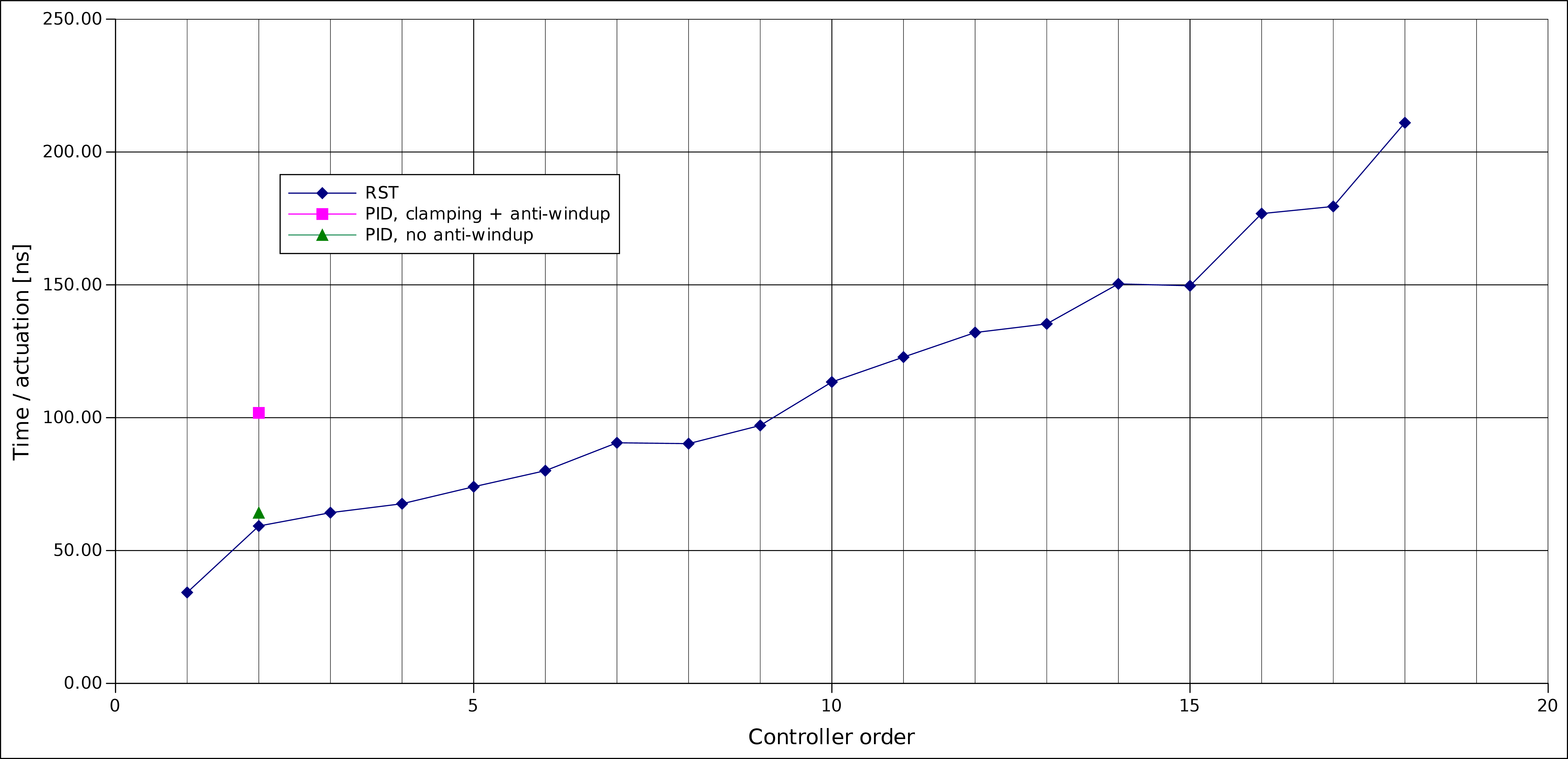
Performance of the controllers depend on their order and the frequency at which the internal automatic anti-windup mechanism is engaged. The general numbers that can be expected for the two controllers are presented in the table below and also as a figure.
Class |
Order |
Anti-windup |
Access time [ns] |
|---|---|---|---|
PID |
2 |
None |
64 |
PID |
2 |
Frequent |
102 |
RST |
1 |
None |
34 |
RST |
2 |
None |
59 |
RST |
3 |
None |
64 |
RST |
4 |
None |
68 |
RST |
5 |
None |
74 |
RST |
6 |
None |
80 |
RST |
7 |
None |
91 |
RST |
8 |
None |
90 |
RST |
9 |
None |
113 |
RST |
10 |
None |
123 |
RST |
11 |
None |
132 |
RST |
12 |
None |
135 |
RST |
13 |
None |
150 |
RST |
14 |
None |
177 |
RST |
15 |
None |
180 |
RST |
16 |
None |
211 |